 انتقل إلى المحتوى
A plug flow reactor (PFR), also called a continuous tubular reactor, is a cylindrical vessel where fluid flows in one direction with complete radial mixing but zero axial back-mixing, so every molecule experiences an identical residence time and uniform reaction conditions from inlet to outlet.
This guide covers PFR design principles and material selection, industrial applications and efficiency advantages, PFR-versus-CSTR performance comparison, factors governing operational efficiency, cleaning and maintenance protocols, scale-up from laboratory to full production, and equipment sourcing strategies.
We explain how flow pattern control, construction in materials like 316L stainless steel and Hastelloy C-276, and pressure-temperature management form the engineering foundation of every PFR installation. Material choices must satisfy ASME Section VIII, the Pressure Equipment Directive (PED), and CE marking requirements depending on deployment region.
PFRs dominate continuous chemical processing because they deliver high conversion per unit volume, tight selectivity control, and compact footprints for gas-phase catalytic reactions, continuous nitration, polymerization, and pharmaceutical intermediate synthesis. For most positive-order reactions, a PFR requires a smaller volume than a CSTR to reach equivalent conversion.
Residence time distribution uniformity, turbulent flow maintenance (Reynolds number above 4,000), and proactive pressure drop monitoring through methods like the Ergun equation directly determine product quality and throughput consistency.
Standard Clean-in-Place sequences, predictive condition monitoring, and lifecycle refurbishment-versus-replacement evaluations keep PFR systems running while minimizing unplanned downtime. Scale-up relies on preserving key dimensionless parameters or numbering-up parallel tubes rather than simple geometric enlargement.
What are the essential design principles of a PFR or tubular reactor?
The essential design principles of a PFR or tubular reactor center on flow pattern control, material selection for corrosive and high-temperature service, and pressure-temperature management. The following subsections cover each principle in detail.
How does the flow pattern in a PFR differ from other reactor types?
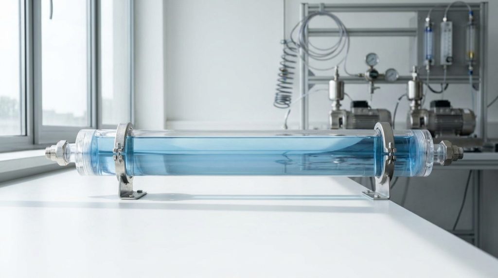
The flow pattern in a PFR differs from other reactor types by eliminating axial back-mixing while maintaining complete radial mixing within each cross-sectional “plug” of fluid. In a CSTR, incoming feed instantly blends with reactor contents, creating a uniform but diluted concentration. A PFR maintains a concentration gradient along the tube length, so each fluid element experiences a uniform residence time.
Turbulent flow (Reynolds number above 4,000) promotes the radial mixing needed to approximate ideal plug flow conditions. Because 316L stainless steel has a thermal conductivity of approximately 15 W/m·K at 100°C (212°F), significantly lower than carbon steel, engineers must design adequate external heat transfer surfaces to manage exothermic reactions without creating radial temperature gradients that disrupt plug flow behavior.
What materials and construction considerations are important for PFRs?
The materials and construction considerations important for PFRs depend on process chemistry, operating temperature, and pressure requirements. Common construction materials include:
- الفولاذ المقاوم للصدأ 316L provides broad corrosion resistance and is ASME-approved for service up to 1500°F (816°C), though creep limits restrict practical continuous use at lower temperatures.
- هاستيلوي سي-276 delivers exceptional resistance in oxidizing and reducing environments, with corrosion rates below 0.05 mm/year in boiling 10% sulfuric acid.
- الفولاذ المبطن بالزجاج suits corrosive processes up to 500°F (260°C) for standard formulations, or 650°F (343°C) with high-temperature glass.
- PTFE linings protect against aggressive chemicals at temperatures up to 260°C (500°F) under positive pressure.
- Alloy 230 (nickel-chromium-tungsten-cobalt) handles extreme thermal service up to 980°C (1796°F).
Construction must comply with ASME Section VIII (Division 1 or 2), the Pressure Equipment Directive (PED) with CE marking for European service, and UKCA marking for United Kingdom installations. Material traceability and weld qualification records are essential for regulatory compliance across jurisdictions.

How do pressure and temperature impact PFR operations?
Pressure and temperature impact PFR operations by directly determining allowable wall thickness, material selection, and reactor lifespan. Higher operating pressures require thicker tube walls or higher-strength alloys, while elevated temperatures reduce allowable stress values for all metallic materials.
Key temperature and pressure limits by material:
| Material | Max Temperature | Allowable Stress (at elevated temp) | Governing Standard |
| 316L SS (UNS S31603) | 1500°F (816°C) | Creep-limited above 600°C | ASME Section II Part D |
| Hastelloy C-276 (UNS N10276) | 1250°F (677°C) | 23.1 ksi (159 MPa) at 800°F (427°C) | ASME Section VIII-1 |
| PTFE lining | 500°F (260°C) | Restricted under vacuum above 150°C | Manufacturer specs |
| Alloy 230 | 1796°F (980°C) | Superior thermal stability | ASME-approved |
According to Little P.Eng. Engineering Services, ASME Section II Part D governs allowable stresses for 316L up to 1500°F (816°C), though practical design typically stays below creep-onset temperatures. For most PFR applications, selecting the right material-temperature pairing at the design stage prevents costly mid-life replacements and unplanned shutdowns.
With material and pressure boundaries established, understanding why PFRs dominate industrial chemical processing reveals their practical advantages.
Why are PFRs commonly used in industrial chemical processing?
PFRs are commonly used in industrial chemical processing because they deliver high conversion rates, predictable residence times, and compact footprints for continuous production. The following sections cover ideal reaction types, efficiency advantages, and built-in safety features.

What types of reactions are best suited for PFRs?
The types of reactions best suited for PFRs are fast, continuous, and well-characterized chemistries where uniform residence time directly influences product quality. These include:
- Gas-phase catalytic reactions such as Fischer-Tropsch synthesis and methanol production
- Highly exothermic reactions like nitration and polymerization, where controlled heat removal along the tube length prevents thermal runaway
- High-conversion reactions where positive-order kinetics favor the concentration gradient maintained in plug flow
- Continuous hydrogenation and oxidation processes requiring tight selectivity control
Reactions with rapid kinetics benefit most because the absence of back-mixing preserves the driving force for conversion along the entire reactor length. For processes demanding consistent product distribution, PFRs remain the preferred continuous reactor configuration.
How do PFRs enhance reaction efficiency and product yield?
PFRs enhance reaction efficiency and product yield by eliminating back-mixing, which preserves a high concentration driving force along the full reactor length. According to course notes from the University of Manchester, the ratio of CSTR volume to PFR volume increases significantly at high conversion levels for first-order reactions, highlighting the efficiency advantage of PFRs in minimizing space-time requirements.
This volume advantage translates directly to smaller equipment footprints, lower capital expenditure, and reduced energy consumption per unit of product. For procurement engineers evaluating reactor investments, the space-time efficiency of a PFR often justifies its selection over a CSTR when target conversions exceed 80%.
What safety features are typically incorporated in PFR design?
The safety features typically incorporated in PFR design include:
- Pressure relief valves and rupture discs sized per ASME Section VIII or PED 2014/68/EU requirements
- External cooling jackets or heat-exchange shells that remove exothermic heat continuously along the tube length
- Advanced sealing systems designed to minimize volatile organic compound (VOC) leaks during operation
- Temperature and pressure sensors at multiple axial positions for real-time monitoring
- Emergency quench injection ports that rapidly dilute or cool the reaction mixture
The continuous, enclosed geometry of a PFR inherently limits the reactive inventory at any single point, reducing the consequences of a containment failure compared to large-volume batch vessels. This lower holdup volume per unit of throughput makes PFRs a safer choice for hazardous chemistries such as nitration or high-pressure hydrogenation.
With these processing advantages established, understanding how PFR performance compares directly to a CSTR clarifies reactor selection decisions.
How does the operation of a PFR compare to a continuous stirred tank reactor (CSTR)?
The operation of a PFR compares to a CSTR primarily in mixing behavior, volume efficiency, and conversion performance. The following subsections cover advantages, disadvantages, and preferred scenarios for each reactor type.
What are the advantages and disadvantages of using a PFR versus a CSTR?
The advantages of using a PFR versus a CSTR include higher conversion per unit volume, narrower residence time distribution, and better selectivity for positive-order reactions. According to MIT OpenCourseWare, for most positive-order reactions, a PFR requires a smaller volume than a CSTR to achieve the same degree of conversion under identical reaction conditions.
PFR disadvantages include:
- Difficulty handling highly viscous fluids or slurries
- Limited flexibility for multi-product campaigns
- Higher pressure drop across the reactor length
- Challenging temperature control for strongly exothermic reactions
CSTR advantages include:
- Uniform composition simplifies temperature control
- Easy adaptation to multi-product or variable-feed operations
- Lower pressure drop due to large vessel geometry
- Simpler cleaning and inspection access
CSTR disadvantages include larger volume requirements at high conversions and diluted reactant concentration due to back-mixing, which reduces driving force for reaction kinetics.
In which scenarios is a PFR preferred over a CSTR?
A PFR is preferred over a CSTR in scenarios requiring high conversion, tight product selectivity, or continuous large-volume throughput. Fast, irreversible reactions benefit most from plug flow because the absence of back-mixing maintains high reactant concentration along the reactor length.
Specific scenarios favoring PFR selection include:
- Gas-phase catalytic reactions such as Fischer-Tropsch synthesis or methanol production
- High-conversion polymerization where back-mixing degrades molecular weight distribution
- Continuous pharmaceutical manufacturing where narrow residence time ensures consistent product quality
- Reactions with positive-order kinetics operating above 80% target conversion
When flexibility, frequent product changeovers, or slow liquid-phase reactions dominate process requirements, a CSTR remains the more practical choice. For procurement engineers evaluating continuous reactor assets, understanding these operational boundaries guides specification decisions.
What factors influence performance and efficiency in a PFR?
Performance and efficiency in a PFR depend on residence time distribution, flow regime stability, and pressure drop management. The following sections address how each factor affects reactor output.
How does residence time distribution affect product quality in a PFR?
Residence time distribution (RTD) affects product quality in a PFR by determining whether all fluid elements experience identical reaction times. In an ideal PFR, every molecule spends the same duration inside the reactor, producing uniform conversion and consistent product specifications. When RTD deviates from this ideal, some material over-reacts while other material under-reacts, creating off-spec product and reducing yield.
This consistency matters particularly in pharmaceutical manufacturing. The FDA’s Center for Drug Evaluation and Research (CDER), noted that “adopting continuous manufacturing for pharmaceutical production will reduce drug product quality issues, lower manufacturing costs, and improve availability of quality medicines to patients.” Tight RTD control is therefore essential for regulated industries where batch-to-batch variability is unacceptable.
What are common challenges in maintaining optimal flow regimes?
Common challenges in maintaining optimal flow regimes include:
- Velocity profile distortion from laminar conditions, where parabolic flow creates unequal residence times across the tube cross-section.
- Insufficient radial mixing at low Reynolds numbers, preventing the homogeneous conditions that approximate plug flow.
- Dead zones and channeling caused by poor inlet distribution or internal obstructions.
- Temperature gradients along the reactor wall that alter local viscosity and disrupt uniform flow.
Turbulent conditions (Re > 4,000) promote the radial mixing needed for near-ideal plug flow, but achieving turbulence requires sufficient fluid velocity relative to tube diameter. For viscous feedstocks, static mixers or narrower tube geometries can compensate.
How can fouling and pressure drop be managed in PFR systems?
Fouling and pressure drop can be managed in PFR systems through proper design, material selection, and monitoring protocols. The Ergun equation provides the standard method for predicting single-phase pressure loss in packed-bed configurations, correlating it to fluid velocity, particle diameter, and bed porosity.
According to Wiley Online Library, two-phase pressure drops in trickle-bed reactors are considered high when they exceed 0.1 atm/m (approximately 0.5 psi/ft), often requiring specific correlations beyond the standard Ergun equation.
Practical fouling mitigation strategies include:
- Polished internal surfaces to reduce deposition sites.
- Periodic thermal or chemical cleaning cycles before pressure drop exceeds design limits.
- Inline differential pressure monitoring to detect fouling onset early.
Proactive pressure drop management prevents unplanned shutdowns, which is critical given that downtime in continuous processes compounds rapidly into lost production and off-spec material.
With performance factors understood, proper cleaning and maintenance protocols keep these systems operating at peak efficiency.
How are PFRs cleaned, maintained, and refurbished in industrial settings?
PFRs are cleaned, maintained, and refurbished through standardized protocols including Clean-in-Place systems, predictive monitoring, and lifecycle cost evaluations. The following subsections cover standard procedures, downtime reduction, and refurbishment decisions.
What are standard maintenance procedures for PFRs?
Standard maintenance procedures for PFRs include scheduled inspections, Clean-in-Place (CIP) cycles, and pressure integrity testing. CIP procedures typically follow a 5-step sequence:
- Pre-rinse to remove bulk residue.
- Caustic wash using 1–2% NaOH at 158–185°F (70–85°C).
- Intermediate rinse with purified water.
- Acid wash using 0.5–1.5% HNO₃ or H₃PO₄.
- Final rinse with purified water to verify cleanliness.
Inspection intervals follow ASME Section VIII and PED requirements, covering wall thickness measurements and weld integrity checks. For pharmaceutical applications, facilities often add Sterilization-in-Place (SIP) using high-temperature steam after CIP completion. Regular pressure drop monitoring across the tube length also helps detect early fouling or catalyst degradation before performance losses accumulate.

How is downtime minimized during PFR maintenance or cleaning?
Downtime during PFR maintenance or cleaning is minimized through predictive maintenance scheduling, automated CIP systems, and modular design strategies that allow section-by-section servicing. According to a 2025 manufacturing maintenance report from Oxmaint, unplanned downtime costs the world’s 500 largest manufacturers approximately $1.4 trillion annually, equivalent to 11% of their total revenue.
Effective downtime reduction strategies include:
- Implementing condition-based monitoring with pressure, temperature, and flow sensors to predict failures before they occur.
- Using parallel reactor trains so one unit can be isolated for cleaning while others remain operational.
- Adopting digital technologies for real-time diagnostics, which the OECD identifies as capable of significantly reducing downtime costs otherwise worsened by equipment failure during use phases.
For process engineers managing continuous production, even a few hours of unplanned shutdown can cascade through downstream operations. Investing in automated monitoring and modular PFR configurations typically delivers the fastest return on reliability improvements.
When is refurbishment versus replacement the better option for PFRs?
Refurbishment is the better option for PFRs when the reactor shell and primary pressure boundary remain structurally sound, while replacement becomes necessary when material degradation, corrosion allowance exhaustion, or code compliance gaps exceed economical repair thresholds. A 2025 study published in Nuclear Technology (Taylor & Francis) on advanced reactor lifecycle management describes a “build-to-replace” strategy that evaluates replacement versus refurbishment schedules to optimize operations and maintenance costs over the equipment lifecycle.
Key factors in the refurbishment-versus-replacement decision include:
- Remaining wall thickness relative to minimum design requirements per ASME Section VIII or EN 13445.
- Availability of replacement internals, catalyst tubes, or linings versus full-unit lead times.
- Total cost of requalification inspections, hydrostatic testing, and recertification compared to new-unit procurement.
- Whether the existing reactor footprint and nozzle configuration match current process requirements.
Sourcing quality used or new surplus PFR equipment through established suppliers like International Process Plants can bridge the gap when refurbishment costs approach replacement thresholds but lead times for new fabrication are prohibitive.
What role does scale (lab, pilot, full-scale) play in PFR design and deployment?
Scale plays a central role in PFR design and deployment because each stage, from laboratory to pilot to full-scale, introduces distinct challenges in heat transfer, flow distribution, and reaction kinetics that must be resolved before commercial operation.
How are laboratory or pilot PFRs scaled up for industrial use?
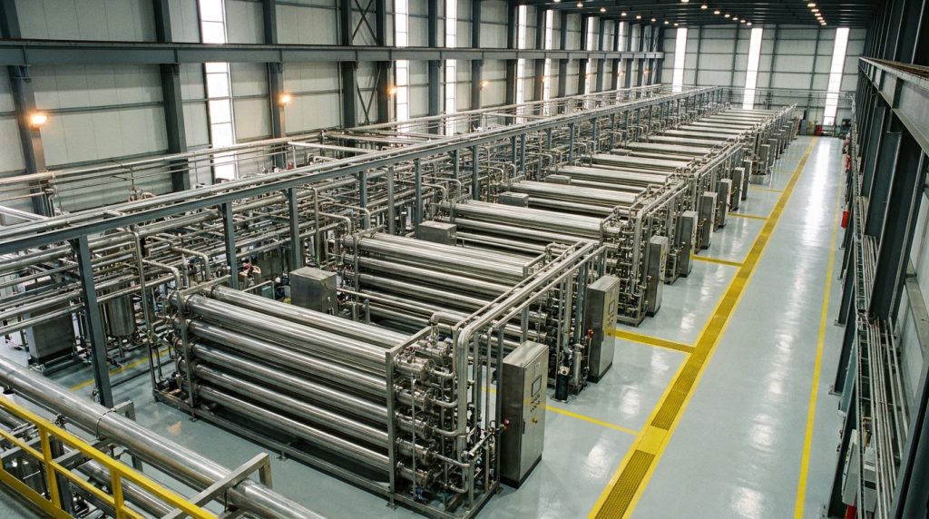
Laboratory or pilot PFRs are scaled up for industrial use through two primary approaches: traditional geometric scaling and numbering up. Traditional scaling increases tube diameter and length while preserving key dimensionless parameters such as the Damköhler number (Da), which represents the ratio of reaction rate to mass transport rate and serves as a primary criterion for sizing unidirectional flow reactors. According to a study published in Heliyon (Cell Press), the Damköhler number is the primary criterion for the sizing and scale-up of unidirectional flow reactors and CSTRs. For micro- and milli-reactors, numbering up (running multiple identical small tubes in parallel) often replaces geometric scaling to maintain plug flow performance characteristics at production volumes.
What are the challenges of scaling PFR operations?
The challenges of scaling PFR operations include maintaining uniform flow distribution, managing heat removal in larger-diameter tubes, and preserving the narrow residence time distribution achieved at bench scale.
Key scale-up challenges include:
- Maintaining turbulent flow (Re > 4,000) across all parallel tubes when numbering up.
- Preventing hot spots as tube diameter increases, since heat transfer surface-to-volume ratio decreases with scale.
- Preserving plug flow behavior (Pe > 100) when length-to-diameter ratios change.
- Meeting pressure vessel codes such as ASME Section VIII, the Pressure Equipment Directive (PED), and CE marking requirements at full-scale wall thicknesses.
- Achieving consistent catalyst packing density in packed-bed configurations across longer tube lengths.
For many process engineers, the transition from pilot to full-scale represents the highest-risk phase because small deviations in flow uniformity compound across hundreds of parallel tubes, making pre-commissioning flow testing essential.
With scale-up principles established, selecting the right equipment and sourcing strategy becomes the final step in successful PFR deployment.
How should you approach PFR selection and asset redeployment with International Process Plants?
International Process Plants provides global support for acquiring, selling, and redeploying used PFRs and related process equipment. The following sections cover our capabilities and summarize the key principles discussed throughout this article.
Can International Process Plants assist with acquiring or selling used PFRs and related equipment?
Yes, International Process Plants can assist with acquiring or selling used PFRs and related equipment. With over 46 years of experience and an inventory exceeding 10,000 pieces of new surplus and quality used process equipment, we simplify plant transitions for chemical, pharmaceutical, and petrochemical operations worldwide.
Proper equipment selection requires a solid technical base for sizing and operational sequencing. The World Bank notes that less than one in three industrial plants in developing regions successfully scales up indigenous industries due to a lack of such technical foundations. International Process Plants addresses this gap by offering engineering-grade documentation, inspection records, and compliance verification for equipment built to ASME Section VIII, PED, and CE marking standards.
Our warehouses in South Carolina (US), Germany, and the United Kingdom support rapid deployment across global markets. Whether you need a tubular reactor system, associated heat exchangers, or complete continuous flow process lines, International Process Plants manages the full asset redeployment cycle from evaluation through delivery.
What are the key takeaways about how a PFR or tubular reactor works covered in this article?
The key takeaways about how a PFR or tubular reactor works covered in this article are:
- A PFR achieves ideal plug flow through zero axial mixing and complete radial mixing, with turbulent flow (Re > 4,000) promoting this behavior.
- PFRs require smaller volumes than CSTRs for positive-order reactions at equivalent conversion levels.
- Materials such as 316L stainless steel and Hastelloy C-276 enable operation across demanding temperature and corrosion conditions.
- The Ergun equation is the standard method for calculating pressure drop in packed-bed tubular reactors, correlating pressure loss to fluid velocity, particle diameter, and bed porosity.
- Scale-up strategies include numbering-up approaches to preserve plug flow characteristics at production volumes.
- Routine CIP/SIP protocols and preventive maintenance minimize unplanned downtime costs.
For procurement engineers evaluating used or new surplus PFR systems, International Process Plants offers the technical expertise and currently available inventory to match equipment specifications with process requirements.

 AR
AR  EN
EN  ES
ES  FR
FR  PL
PL  DE
DE  UR
UR  HI
HI  NL
NL  TR
TR  IT
IT  UK
UK  RU
RU  JA
JA  PT
PT  ZH
ZH