 Skip to content
Agitator and impeller selection for reactors is the engineering process of matching impeller geometry, power input, and materials of construction to a specific vessel’s design constraints and process requirements.
This guide covers reactor design and fluid property considerations, impeller types and flow patterns, sizing calculations and scale-up criteria, common selection challenges, and sourcing pre-configured reactor systems.
Reactor geometry sets the foundation for every agitator specification. Tank diameter determines impeller-to-tank ratios (typically 0.33 for standard mixing), while vessel internals like baffles, coils, and dip tubes constrain clearance and flow paths. High-viscosity systems above 25,000 cP (25 Pa·s) require close-clearance impellers such as helical ribbons or anchors that operate in the laminar regime.
Impeller types differ significantly in shear intensity and power consumption. Rushton turbines deliver high shear at a power number of approximately 5.00 for gas dispersion, while hydrofoil impellers maximize axial pumping at power numbers as low as 0.30. Pitched-blade turbines offer a middle path, combining axial and radial flow at a power number near 1.30.
Sizing relies on dimensionless parameters including Reynolds number, power number, and tip speed, with motor selection following the 85% load rule to accommodate startup torque and viscosity changes. Scale-up forces trade-offs because maintaining constant power per unit volume increases tip speed, while holding tip speed constant reduces mass transfer capacity.
Material compatibility and correct impeller placement prevent failures ranging from dead zones caused by insufficient bottom clearance to corrosion-driven component degradation. Alloys such as 316L stainless steel and Hastelloy C-276 address different chemical environments, and specifications should reference ASME Section VIII or PED standards.
International Process Plants maintains over 10,000 pieces of equipment, with much of our reactor inventory consisting of batch reactors already equipped with matched agitation systems, reducing specification risk and accelerating project timelines.
What Factors Influence Agitator and Impeller Selection in Reactors?
Agitator and impeller selection in reactors depends on reactor geometry, process objectives, fluid properties, and operating conditions. The following subsections cover how each factor shapes the choice of mixing equipment.
How Does Reactor Design Affect Agitator and Impeller Choice?
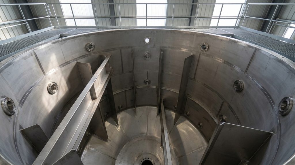
Reactor design affects agitator and impeller choice by constraining geometric ratios, vessel scale, and internal configurations that determine which impeller types can operate effectively. Tank diameter sets the baseline for impeller sizing, baffle placement, and liquid height parameters.
Scale also matters significantly. Bioreactor scale-up from 1–2 L (0.26–0.53 gal) bench-top units to production scale must account for oxygen transfer rates and the potential for impeller tip damage to shear-sensitive cells, according to Doran (via the Encyclopedia of Chemical Processing). Vessel internals such as dip tubes, coils, and baffle geometry further limit impeller clearance and flow patterns. High-viscosity systems above 25,000 cP (25 Pa·s) require helical ribbon or anchor impellers that operate in the laminar regime to ensure bulk movement, making vessel aspect ratio a critical constraint.
Why Are Process Objectives Important When Choosing an Agitator or Impeller?
Process objectives are important when choosing an agitator or impeller because they define the required mixing outcome, which directly determines impeller geometry, speed, and power input. Different objectives demand different flow characteristics:
- Solid suspension requires strong axial flow and sufficient bottom clearance.
- Gas dispersion needs high-shear radial impellers to break gas into fine bubbles.
- Blending of miscible liquids prioritizes bulk turnover at lower power input.
- Heat transfer enhancement demands flow patterns that sweep vessel walls uniformly.
- Emulsification requires controlled shear to achieve target droplet size distributions.
Selecting an impeller without defining the primary process objective risks oversizing the motor or underperforming on the critical mixing duty.
What Role Do Fluid Properties Play in Agitator and Impeller Selection?
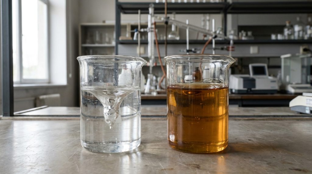
Fluid properties play a central role in agitator and impeller selection because viscosity, density, and rheological behavior determine flow regime, power draw, and impeller effectiveness. Low-viscosity Newtonian fluids operate in the turbulent regime with standard turbine impellers, while high-viscosity or non-Newtonian fluids shift mixing into the transitional or laminar regime, requiring entirely different impeller geometries.
According to research published on Academia.edu, agitation in non-Newtonian fluids follows a shear rate characterized by the Metzner-Otto constant, typically around k = 11, independent of tank-to-impeller diameter ratio. This means viscosity changes with shear rate in ways that standard correlations cannot capture without rheological testing. Fluids exhibiting shear-thinning, thixotropic, or viscoelastic behavior often need close-clearance impellers to maintain consistent motion throughout the vessel.
How Do Temperature and Pressure Conditions Impact Selection?
Temperature and pressure conditions impact selection by imposing mechanical and metallurgical limits on agitator components, shaft seals, and impeller materials. High-temperature processes above 400 °F (204 °C) require alloys with verified creep resistance, while cryogenic applications demand materials that retain ductility at low temperatures.
Pressure affects seal design most directly. Reactors operating under elevated pressures, such as those built to ASME Section VIII or PED (Pressure Equipment Directive) standards, require mechanical seals rated for the full design pressure rather than simple packing glands. Thermal cycling introduces fatigue stress on shaft connections and impeller hubs, particularly in batch reactors that undergo repeated heat-up and cool-down cycles. Matching seal type, bearing configuration, and material grade to the full range of operating temperature and pressure prevents premature failure and unplanned downtime.
Understanding these selection factors provides the foundation for evaluating specific impeller types and their performance characteristics.
What Are the Main Types of Agitators and Impellers Used in Reactors?
The main types of agitators and impellers used in reactors include Rushton turbines, pitched-blade turbines, hydrofoil impellers, anchor impellers, and helical ribbons. Each type differs in flow pattern, shear intensity, and power consumption.
What Are the Advantages and Disadvantages of Common Impeller Types?
The advantages and disadvantages of common impeller types depend on their power number, flow pattern, and suitability for specific process conditions. Key comparisons include:
- Rushton turbines deliver high shear with a power number (Po) of approximately 5.00, making them effective for gas dispersion, but they consume significantly more energy than axial-flow designs.
- Hydrofoil impellers produce efficient axial flow with power numbers as low as 0.30, minimizing energy use, though they lack the shear intensity needed for gas-liquid dispersion.
- Pitched-blade turbines offer a balance of axial and radial flow at a Po of approximately 1.30, providing versatility at moderate power draw, but they may underperform in extreme viscosity or high-shear applications.
- Anchor and helical ribbon impellers handle viscosities above 25,000 cP (25 Pa·s) in laminar regimes, yet their low rotational speeds limit effectiveness in turbulent blending tasks.
For most batch reactor applications, selecting the impeller with the lowest power number that still achieves the required process outcome reduces both capital and operating costs.
How Do You Differentiate Between Axial and Radial Flow Impellers?
You differentiate between axial and radial flow impellers by the direction each type discharges fluid relative to the impeller shaft. Axial flow impellers push fluid parallel to the shaft (top-to-bottom circulation), while radial flow impellers discharge fluid perpendicular to the shaft toward the vessel wall.
Pitched-blade turbines (PBT), typically with 45° blades, provide a combination of axial and radial flow with a standard power number of approximately 1.30, according to research published by Tecnic. Standard industrial practice uses four baffles, each with a width of 1/12th to 1/10th of the tank diameter (T), to convert tangential flow into axial flow and prevent vortexing. Without baffles, radial impellers generate a central vortex that reduces mixing effectiveness.
When Should Specialized Impellers Be Considered?
Specialized impellers should be considered when process fluids exceed the operating limits of standard turbine designs. According to ScienceDirect, standard centrifugal pumps typically handle a maximum viscosity of 800 cP (0.8 Pa·s), beyond which specialized high-viscosity impellers like anchors or helical ribbons are required.
Additional conditions that warrant specialized designs include:
- Shear-sensitive biological cultures or crystal slurries requiring controlled tip speed.
- Non-Newtonian fluids where viscosity changes with shear rate.
- Gas-liquid-solid three-phase systems needing combined dispersion and suspension.
- Reactors operating under high pressure per ASME Section VIII or PED standards, where mechanical seal design constrains impeller weight and speed.
When viscosity, shear sensitivity, or multiphase complexity exceeds standard impeller capabilities, early specification of specialized designs prevents costly retrofits during scale-up.
How Do You Size and Specify Agitators and Impellers for Reactor Performance?
You size and specify agitators and impellers for reactor performance by calculating dimensionless numbers, determining power draw, and applying scale-up criteria. The following sections cover the core calculations, power requirements, and scale-up challenges involved.
What Calculations Are Involved in Agitator Sizing?
The calculations involved in agitator sizing center on dimensionless numbers that characterize flow regime and energy input. The impeller Reynolds number (Re) is calculated as Re = (D² × N × ρ) / μ, where D is impeller diameter (m or ft), N is rotational speed (rev/s), ρ is fluid density (kg/m³ or lb/ft³), and μ is dynamic viscosity (Pa·s or cP). This value determines whether flow is laminar (Re < 10) or fully turbulent (Re > 10,000).
Additional key calculations include:
- Power number (Np) = P / (ρ × N³ × D⁵), which remains constant in the turbulent regime.
- Tip speed (Utip) = π × N × D (m/s or ft/s), serving as the primary shear limit for sensitive cultures and crystals.
- Impeller-to-tank diameter ratio (D/T), typically 0.33 for standard mixing.
How Do Power Requirements Affect Selection?
Power requirements affect selection by determining motor size, mechanical seal ratings, and gearbox specifications. According to the Handbook of Chemical Engineering Calculations (Chopey), the actual power requirement (Pactual) is recommended as P/0.85 (kW or HP), ensuring motor load does not exceed 85% of rated capacity.
This 85% rule accounts for startup torque, viscosity increases during reactions, and safety margins for process upsets. Undersizing the motor leads to overheating and premature failure; oversizing wastes capital and energy. Engineers should verify that shaft diameter, seal pressure ratings per ASME Section VIII, and bearing life all align with the calculated power draw before finalizing the specification.
Why Is Scale-Up a Challenge in Agitator and Impeller Specification?
Scale-up is a challenge in agitator and impeller specification because you cannot maintain all dimensionless parameters simultaneously when vessel geometry increases. Common scale-up strategies include maintaining constant power per unit volume (P/V = constant) for mass transfer applications or constant tip speed (Utip = constant) for shear-controlled processes.
Holding P/V constant preserves reaction kinetics but increases tip speed at larger diameters, potentially damaging shear-sensitive cells or crystals. Conversely, holding tip speed constant reduces P/V, which can starve oxygen transfer in aerobic fermentations. Bioreactor scale-up from bench-top units of 1–2 L (0.26–0.53 gal) to production scale must balance oxygen transfer rates against impeller tip damage. No single criterion satisfies every process objective, so engineers typically prioritize the rate-limiting parameter and accept trade-offs elsewhere.
With sizing and scale-up principles established, understanding common challenges helps prevent costly specification errors.
What Common Challenges Occur in Agitator and Impeller Selection for Reactors?
Common challenges in agitator and impeller selection for reactors include poor mixing efficiency, incorrect sizing, and material incompatibility. The following sections address each challenge with practical solutions.
How Can Mixing Efficiency Be Improved in Reactor Operations?
Mixing efficiency can be improved in reactor operations by optimizing baffle configuration, impeller placement, and flow patterns. Standard industrial practice uses four baffles, each with a width of 1/12th to 1/10th of the tank diameter (T), to convert tangential flow into axial flow and prevent vortexing, according to CollegeManzil’s engineering reference.
Key strategies to improve mixing efficiency include:
- Installing baffles at proper spacing to eliminate swirling and dead zones.
- Positioning impellers at correct bottom clearance to promote full tank circulation.
- Matching impeller type to the dominant flow regime (turbulent, transitional, or laminar).
- Verifying that the liquid level to tank diameter ratio remains close to 1:1 for effective blending.
Without proper baffling, reactors develop a central vortex that wastes energy while leaving peripheral zones unmixed. For most batch reactor operations, combining axial-flow impellers with correctly sized baffles delivers the most uniform blend times.
What Problems Arise from Incorrect Agitator or Impeller Sizing?
Problems that arise from incorrect agitator or impeller sizing include dead zones, excessive power consumption, mechanical failure, and inconsistent product quality. Incorrect impeller placement, specifically a bottom clearance (C) that is too low, leads to dead zones where solids accumulate and cannot be suspended, as documented by MXD Process.
Common consequences of improper sizing:
- Undersized impellers fail to achieve full suspension, causing solids to settle at the vessel bottom.
- Oversized impellers draw excessive power, overload motor drives, and create damaging vibration in the shaft and seal assembly.
- Incorrect tip speed damages shear-sensitive products such as biological cultures and crystalline structures.
- Motor loads exceeding rated capacity accelerate wear on gearboxes and couplings.
Procurement engineers should verify that impeller diameter, rotational speed, and motor rating are specified together as a matched system. Evaluating one parameter in isolation often leads to costly rework during commissioning.
How Does Material Compatibility Influence Selection?
Material compatibility influences selection by determining whether agitator and impeller components can withstand the chemical environment, operating temperature, and pressure conditions inside the reactor. Glass-lined reactors provide extreme chemical compatibility but are limited to operating pressures of roughly 3 atm (44 PSI or 3.03 bar) and are highly susceptible to thermal shock if temperature gradients exceed 100°C (212°F), according to Jinzong Machinery.
Critical material considerations include:
- 316L stainless steel suits most organic solvents and mild acids at moderate temperatures.
- Hastelloy C-276 resists pitting and stress corrosion cracking in highly oxidizing and reducing environments.
- Glass-lined surfaces handle strong acids but cannot tolerate rapid thermal cycling or mechanical impact from agitator components.
- PTFE-coated impellers protect against corrosive media but have lower temperature limits than metal alternatives.
Material selection must account for both the process fluid and the mechanical stresses imposed by agitation. An impeller alloy that resists corrosion under static conditions may still fail under the combined effects of high shear, elevated temperature, and cyclic fatigue loading. Specifications should reference standards such as ASME Section VIII and the Pressure Equipment Directive (PED) to ensure wetted components meet pressure and material certification requirements.
With these challenges addressed, sourcing reactor vessels equipped with properly matched agitators becomes the next practical step.

How Should You Approach Agitator and Impeller Selection for Reactors with Process Equipment Solutions from International Process Plants?
You should approach agitator and impeller selection for reactors with International Process Plants by leveraging our inventory of new surplus and quality used batch reactors pre-configured with proven agitation systems. The following sections cover how IPP helps with selection and key takeaways.
Can Comprehensive Plant and Equipment Solutions from IPP Help With Agitator and Impeller Selection?
Yes, comprehensive plant and equipment solutions from IPP can help with agitator and impeller selection. International Process Plants currently maintains an inventory of over 10,000 pieces of equipment, with much of our reactor inventory consisting of batch reactors equipped with agitation systems already sized and matched to vessel geometry. This eliminates the engineering burden of specifying impeller-to-tank diameter ratios, which for turbine agitators reach up to 0.6 with liquid depth equal to the tank diameter (H/T = 1.0).
According to Mordor Intelligence, the industrial mixers market is expected to expand from USD 2.88 billion in 2025 to USD 4.48 billion by 2031 at a 6.1% CAGR, reflecting growing demand for properly configured mixing systems. International Process Plants addresses this demand by offering reactors in verified materials including 316L, 316, 304, and 304L stainless steel, as well as Hastelloy C-276, with equipment stored across warehouses in South Carolina, Germany, and the United Kingdom.
What Are the Key Takeaways About Agitator and Impeller Selection for Reactors We Covered?
The key takeaways about agitator and impeller selection for reactors are:
- Process objectives determine impeller type: mass transfer applications require constant power per unit volume (P/V), while shear-controlled processes maintain constant tip speed.
- Fluid viscosity drives geometry: low-viscosity Newtonian fluids use turbines or hydrofoils, while high-viscosity systems above 25,000 cP (25 Pa·s) require helical ribbons or anchors.
- Vessel geometry constrains impeller sizing: the D/T ratio, bottom clearance, and baffle configuration must align with the chosen impeller’s flow pattern.
- Material compatibility matters: reactors handling corrosive media need alloys like Hastelloy C-276 or glass-lined vessels rated to appropriate pressure and temperature limits.
- Scale-up introduces thermal complexity: mechanical power from agitators converts to heat in high-viscosity fluids, adding to the process heat load.
Sourcing a reactor with a pre-matched agitation system from International Process Plants reduces specification risk and accelerates project timelines compared to configuring components independently.

 EN
EN  ES
ES  FR
FR  PL
PL  DE
DE  AR
AR  UR
UR  HI
HI  NL
NL  TR
TR  IT
IT  UK
UK  RU
RU  JA
JA  PT
PT  ZH
ZH